ETH-03 以太网帧结构介绍以及 Verilog 实现代码
什么是以太网帧
以太网帧是指在网络中传输数据的基本单位。以太网帧按照一定的格式组成了以太网数据包。简单来讲,它类似于 “数据包裹(就像快递一样)”,包裹中包含了 “寄件人 (发送方 MAC 地址)”、”收件人 (接收方 MAC 地址)” 和 “包裹内容 (有效数据)”。以太网帧指的就是这个数据包本身。
理解以太网帧的组成是我们开始学习以太网 ARP、ICMP、UDP 等上层协议的基础。
以太网帧的组成 (格式)
数据格式如下图所示。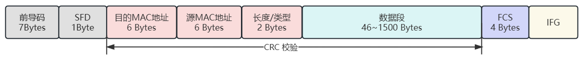
- 前导码 (Preamble):固定的 7 字节 0x55,二进制表现为 0 和 1 交替。
- 帧起始界定符 (SFD):全称:Start Frame Delimiter。固定的 1 字节 0xD5,二进制表现为
1101_1010 - 目的 MAC 地址:即接收端的物理 MAC 地址,占用 6 个字节,MAC 地址从应用上可分为以下三种类型
- 单播地址:第一个字节的最低位为 0,比如
00:00:00:11:11:11一般用于标志唯一的设备 - 组播地址:第一个字节的最低位为 1,比如
01:00:00:11:11:11一般用于标志同属一组的多个设备 - 广播地址:所有的 48 bit 全部为 1,即
FF:FF:FF:FF:FF:FF,它用于标志同一网段中的所有设备
- 单播地址:第一个字节的最低位为 0,比如
- 源 MAC 地址:即发送端的 MAC 地址,占用 6 个字节
- 长度/类型:当这两个字节的值小于 1500 (对应十六进制 0x05DC) 时,代表该以太网数据包中的数据段长度;大于 1500 (对应十六进制 0x05DC) 时,代表以太网中的数据属于某个 上层协议。例如,0x0800 代表 IP 协议 (国际协议)、0x0806 代表 ARP 协议 (地址解析协议) 等,其余内容会在 以太网数据类型 这个表中列出
- 数据段:长度最小46个字节,最大1500个字节。
- 最大值 1500 称为以太网的最大传输单元(MTU,Maximum Transmission Unit),之所以限制最大传输单元是因为在多个计算机的数据帧排队等待传输时,如果某个数据帧太大的话,接收这一帧的数据所带来的时间开销将会变高,从而导致体验变差。另外还要考虑网络I/O控制器缓存区资源以及网络最大的承载能力等因素,因此最大传输单元是由各种综合因素决定的。
- 为了避免增加额外的配置,通常以太网的有效数据字段都会小于1500个字节,现在电脑的配置已经足够接收巨型帧,巨型帧可以超过 1500 个字节。但是,要成功使用巨型帧,网络中的所有设备(包括交换机、路由器和主机)都必须支持巨型帧,并且 MTU 的大小必须一致。如果网络中的任何设备不支持巨型帧,或者 MTU 的大小不一致,那么数据包可能会被丢弃或者分片,从而影响网络性能。
- 帧检验序列(FCS):全称:Frame Check Sequence。4 个字节的循环冗余校验码 (通常是CRC-32 校验)
- CRC 数据校验从目的 MAC 地址开始计算,直到数据段最后一个数据结束。通用的CRC标准有 CRC-8、CRC-16、CRC-32、CRC-CCIT,其中在网络通信系统中应用最广泛的是 CRC-32 标准。
- 帧间隙(IFG):全称:Interpack Gap。即两帧之间的时间间隔,最小为 96bit time。
- IFG 的最小值是 96 bit time ,即在媒介中发送 96 位原始数据所需要的时间,在不同媒介中 IFG 的最小值是不一样的。不管 10M/100M/1000M 的以太网,两帧之间最少要有 96bit time,IFG 的最少间隔时间计算方法如下:
- 10 Mbps 最小时间是
96*100ns = 9600ns - 100 Mbps 最小时间是
96*10ns = 960ns - 1000 Mbps 最小时间是
96*1ns = 96ns
- 10 Mbps 最小时间是
- IFG 的最小值是 96 bit time ,即在媒介中发送 96 位原始数据所需要的时间,在不同媒介中 IFG 的最小值是不一样的。不管 10M/100M/1000M 的以太网,两帧之间最少要有 96bit time,IFG 的最少间隔时间计算方法如下:
以太网数据类型
在以太网数据包结构中,2 字节类型字段的内容如下表,其中加粗的类型为常用类型。
| Ethertype ( 十六进制 ) |
协议 |
|---|---|
| 0x0800 | 网际协议(IP) |
| 0x0806 | 地址解析协议(ARP : Address Resolution Protocol) |
| 0x0000 - 0x05DC | IEEE 802.3 长度 |
| 0x0101 – 0x01FF | 实验 |
| 0x0600 | XEROX NS IDP |
| 0x0660, 0x0661 | DLOG |
| 0x0801 | X.75 Internet |
| 0x0802 | NBS Internet |
| 0x0803 | ECMA Internet |
| 0x0804 | Chaosnet |
| 0x0805 | X.25 Level 3 |
| 0x0808 | 帧中继 ARP (Frame Relay ARP) [RFC1701] |
| 0x6559 | 原始帧中继(Raw Frame Relay) [RFC1701] |
| 0x8035 | 动态 DARP (DRARP:Dynamic RARP) 反向地址解析协议(RARP:Reverse Address Resolution Protocol) |
| 0x8037 | Novell Netware IPX |
| 0x809B | EtherTalk |
| 0x80D5 | IBM SNA Services over Ethernet |
| 0x 80F 3 | AppleTalk 地址解析协议(AARP:AppleTalk Address Resolution Protocol) |
| 0x8100 | 以太网自动保护开关(EAPS:Ethernet Automatic Protection Switching) |
| 0x8137 | 因特网包交换(IPX:Internet Packet Exchange) |
| 0x 814C | 简单网络管理协议(SNMP:Simple Network Management Protocol) |
| 0x86DD | 网际协议v6 (IPv6,Internet Protocol version 6) |
| 0x880B | 点对点协议(PPP:Point-to-Point Protocol) |
| 0x 880C | 通用交换管理协议(GSMP:General Switch Management Protocol) |
| 0x8847 | 多协议标签交换(单播) MPLS:Multi-Protocol Label Switching [unicast]) |
| 0x8848 | 多协议标签交换(组播)(MPLS, Multi-Protocol Label Switching [multicast]) |
| 0x8863 | 以太网上的 PPP(发现阶段)(PPPoE:PPP Over Ethernet [Discovery Stage]) |
| 0x8864 | 以太网上的 PPP(PPP 会话阶段) (PPPoE,PPP Over Ethernet[PPP Session Stage]) |
| 0x88BB | 轻量级访问点协议(LWAPP:Light Weight Access Point Protocol) |
| 0x88CC | 链接层发现协议(LLDP:Link Layer Discovery Protocol) |
| 0x8E88 | 局域网上的 EAP(EAPOL:EAP over LAN) |
| 0x9000 | 配置测试协议(Loopback) |
| 0x9100 | VLAN 标签协议标识符(VLAN Tag Protocol Identifier) |
| 0x9200 | VLAN 标签协议标识符(VLAN Tag Protocol Identifier) |
| 0xFFFF | 保留 |
实现代码
以太网帧封包模块
该模块负责将来自上层协议的数据,如 ARP、UDP 协议 (包含上层协议的数据头) 等打包成标准的以太网帧,通过 GMII 接口输出。
模块工作方式:
- 上层协议模块将端口
s_axis_tdv拉高,此时封包模块开始发送前导码、SFD、目的 MAC 地址 、源 MAC 地址以及以太网帧类型。 - 当前导内容发送完成后,
s_axis_trdy端口会被拉高,此时可以通过s_axis_td端口写入负载数据。 - 当负载数据写入最后一个字节时,上层协议模块给端口
s_axis_tend一个时钟周期的脉冲信号,结束发送。 - 需要注意的是,上层协议模块给端口
s_axis_tend产生脉冲后,封包模块并不会立即结束发送,而是继续发送 FCS 和等待帧间隙。 module_busy信号在发送数据时 (从前导码开始,到 IFG 结束) 始终为高电平状态。
// NOTE_HEADER--------------------------------------------------------------------------------------
// Useage of this module:
// - Port s_axis_tdv set to 1'b1
// - Wait s_axis_rdy goes to 1'b1, write data to port s_axis_td
// - When data write done, give an pulse signal to s_axis_tend
// NOTE_FOOTER--------------------------------------------------------------------------------------
module eth_frame_encap # (
parameter USE_DEBUG = 1'b0
) (
input wire rst_n , // [I] [ ] reset signal, active-low
// user input interface, (AXI-Stream)
input wire [ 7:0] s_axis_td , // [I] [ 7:0] tx data input
input wire s_axis_tdv , // [I] [ ] tx data valid
input wire s_axis_tend , // [I] [ ] the last data input,
output reg s_axis_trdy , // [O] [ ] tx data ready signal, high logic when module can send data
input wire [47:0] src_mac , // [I] [47:0] Source MAC address to be send
input wire [47:0] dst_mac , // [I] [47:0] Destination MAC address to be send
input wire [15:0] eth_type , // [I] [15:0] Ethernet type (or data length, but we don't need this),
// when its value is less than 1500(Decimal, 0x05DC in hex), it refers to IEEE 802.3 data length (we don't need this)
// when its value is bigger than 1500(Decimal, 0x05DC in hex), it refers to ethernet type
output wire module_busy , // [O] [ ] module busy signal when sending data, active-high
// GMII output interface
input wire gmii_txc , // [I]
output reg [7:0] gmii_txd , // [O]
output reg gmii_tx_en // [O]
);
//================================================================================
// Local Parameter Declarations
//================================================================================
localparam PADDING_DATA = 8'h00 ; // If data segment length is less than 46, padding this data until its length reach to 46.
localparam PREAMBLE_WORD = 8'h55 ;
localparam SFD_WORD = 8'hD5 ;
localparam MIN_FRAME_LEN = 8'd64 ; // Minimum frame length in bytes, includes 6 bytes dest_mac, 6 bytes src_mac, 2 bytes type/length, minum 46 bytes data segment and 4 bytes FCS
localparam HEADER_LENGTH = 8'd14 ; // Ethernet pack header length in bytes, 6 bytes dest_mac, 6 bytes src_mac and 2 bytes type/length
localparam CRC_LENGTH = 8'd4 ; // CRC data length in bytes
localparam MIN_PAYLOAD = 8'd46 ; // Minimum payload length
localparam MAX_PAYLOAD = 16'd1500 ; // Maximum payload length
localparam IFG_CNT = 4'd12 ;
// states defines
localparam ST_IDLE = 4'd0 ; // IDLE state
localparam ST_PREAMBLE = 4'd1 ; // State of sending preamble code, 7 bytes of 0x55
localparam ST_SFD = 4'd2 ; // State of sending SFD, Start Frame Delimiter, 1 byte of 0xd5
localparam ST_DST_MAC = 4'd3 ; // State of sending destination MAC Address
localparam ST_SRC_MAC = 4'd4 ; // State of sending source MAC Address
localparam ST_ETH_TYPE = 4'd5 ; // State of sending Ethernet type
localparam ST_PAYLOAD = 4'd6 ; // State of sending payload, the data content of this packet
localparam ST_PADDING = 4'd7 ; // State of padding data, if data content length is less than 46, then fill data.
localparam ST_CRC = 4'd8 ; // State of sending CRC result
localparam ST_IFG = 4'd9 ; // State of Interpacket GAP, 10Mbps min: 9600ns, 100Mbps min: 960ns, 1000Mbps min: 96ns
//================================================================================
// Register Declarations
//================================================================================
reg [ 3:0] state ;
reg [15:0] byte_cnt ; // counter
reg [15:0] payload_len ;
reg [ 3:0] ifg_cnt ; // IFG counter
reg [ 7:0] crc_data_in ;
reg crc_en ;
reg crc_clr ;
//================================================================================
// Wire Declarations
//================================================================================
wire [31:0] crc_inv ;
wire [31:0] crc_next_inv ;
//================================================================================
// Assign Declarations
//================================================================================
assign module_busy = (state == ST_IDLE) ? 1'b0 : 1'b1 ;
//================================================================================
// implements
//================================================================================
crc32_d8 crc32_d8_inst (
.clk ( gmii_txc ), // [I] [ ] Module clock
.rst_n ( rst_n ), // [I] [ ] Reset signal, active-low
.data ( crc_data_in ), // [I] [ 7:0] The 8-bit data to be validated
.crc_en ( crc_en ), // [I] [ ] CRC enable
.crc_clr ( crc_clr ), // [I] [ ] CRC Result Clear
.crc_next_inv ( crc_next_inv ), // [O] [31:0] CRC data
.crc_inv ( crc_inv ) // [O] [31:0] Inversed crc data
);
//================================================================================
// MAIN CODE
//================================================================================
generate
if (USE_DEBUG == 1'b1) begin: ila_frame_encap
ila_frame_encap ila_frame_encap_inst (
.clk ( gmii_txc ),
.probe0 ( state ), // 4b
.probe1 ( byte_cnt ), // 16b
.probe2 ( payload_len ), // 16b
.probe3 ( gmii_txd ), // 8b
.probe4 ( gmii_tx_en ) // 1b
);
end
endgenerate
always @(posedge gmii_txc or negedge rst_n) begin
if (!rst_n) begin
state <= ST_IDLE ;
crc_en <= 1'b0 ;
crc_clr <= 1'b1 ;
crc_data_in <= 8'b0 ;
s_axis_trdy <= 1'b0 ;
byte_cnt <= 16'b0 ;
ifg_cnt <= 4'b0 ;
gmii_txd <= 8'b0 ;
gmii_tx_en <= 1'd0 ;
payload_len <= 16'd0 ;
end else begin
case(state)
ST_IDLE: begin
payload_len <= 16'd0 ;
crc_en <= 1'b0 ;
crc_clr <= 1'b1 ;
crc_data_in <= 8'b0 ;
byte_cnt <= 16'd0 ;
ifg_cnt <= 4'd0 ;
gmii_txd <= 8'b0 ;
gmii_tx_en <= 1'b0 ;
s_axis_trdy <= 1'b0 ; // Stop receive upstream data
if (s_axis_tdv) begin
state <= ST_PREAMBLE ;
end
end
ST_PREAMBLE: begin
s_axis_trdy <= 1'b0 ;
crc_clr <= 1'b1 ;
crc_en <= 1'b0 ;
gmii_txd <= PREAMBLE_WORD ;
gmii_tx_en <= 1'b1 ;
if (byte_cnt == 7-1) begin
state <= ST_SFD ;
byte_cnt <= 16'd0 ;
end else begin
byte_cnt <= byte_cnt + 1'b1 ;
end
// ... Preamble does not participate in CRC
end
ST_SFD: begin
crc_clr <= 1'b1 ;
crc_en <= 1'b0 ;
s_axis_trdy <= 1'b0 ;
state <= ST_DST_MAC ;
gmii_txd <= SFD_WORD ;
byte_cnt <= 16'd0 ;
// ... SFD does not participate in CRC
end
ST_DST_MAC: begin // Send destination MAC address
crc_clr <= 1'b0 ;
crc_en <= 1'b1 ; // enable crc
s_axis_trdy <= 1'b0 ;
case (byte_cnt)
0: begin gmii_txd <= dst_mac[47:40] ; crc_data_in <= dst_mac[47:40]; end
1: begin gmii_txd <= dst_mac[39:32] ; crc_data_in <= dst_mac[39:32]; end
2: begin gmii_txd <= dst_mac[31:24] ; crc_data_in <= dst_mac[31:24]; end
3: begin gmii_txd <= dst_mac[23:16] ; crc_data_in <= dst_mac[23:16]; end
4: begin gmii_txd <= dst_mac[15:08] ; crc_data_in <= dst_mac[15:08]; end
5: begin gmii_txd <= dst_mac[07:00] ; crc_data_in <= dst_mac[07:00]; end
endcase
// turn to next state
if (byte_cnt == 6 - 1) begin
state <= ST_SRC_MAC ;
byte_cnt <= 16'd0 ;
end else begin
byte_cnt <= byte_cnt + 1'b1 ;
end
end
ST_SRC_MAC: begin // Send destination MAC address
crc_clr <= 1'b0 ;
crc_en <= 1'b1 ; // enable crc
s_axis_trdy <= 1'b0 ;
case (byte_cnt)
0: begin gmii_txd <= src_mac[47:40] ; crc_data_in <= src_mac[47:40]; end
1: begin gmii_txd <= src_mac[39:32] ; crc_data_in <= src_mac[39:32]; end
2: begin gmii_txd <= src_mac[31:24] ; crc_data_in <= src_mac[31:24]; end
3: begin gmii_txd <= src_mac[23:16] ; crc_data_in <= src_mac[23:16]; end
4: begin gmii_txd <= src_mac[15:08] ; crc_data_in <= src_mac[15:08]; end
5: begin gmii_txd <= src_mac[07:00] ; crc_data_in <= src_mac[07:00]; end
endcase
// turn to next state
if (byte_cnt == 6 - 1) begin
state <= ST_ETH_TYPE ;
byte_cnt <= 16'd0 ;
end else begin
byte_cnt <= byte_cnt + 1'b1 ;
end
end
ST_ETH_TYPE: begin
crc_clr <= 1'b0 ;
crc_en <= 1'b1 ; // enable crc
s_axis_trdy <= 1'b0 ;
case (byte_cnt)
0: begin
gmii_txd <= eth_type[15:08] ;
crc_data_in <= eth_type[15:08] ;
s_axis_trdy <= 1'b1 ; // we can receive user data at next clock period
end
1: begin
gmii_txd <= eth_type[07:00] ;
crc_data_in <= eth_type[07:00] ;
end
endcase
// turn to next state
if (byte_cnt == 2 - 1) begin
s_axis_trdy <= 1'b1 ; // we can receive user data at next clock period
state <= ST_PAYLOAD ;
end else begin
byte_cnt <= byte_cnt + 1'b1 ;
end
end
ST_PAYLOAD: begin // axi-stream data in at this time.
if (s_axis_tdv && s_axis_trdy) begin
s_axis_trdy <= 1'b1 ;
crc_clr <= 1'b0 ;
crc_en <= 1'b1 ;
gmii_txd <= s_axis_td ;
crc_data_in <= s_axis_td ;
payload_len <= byte_cnt + 1'b1 ;
byte_cnt <= byte_cnt + 1'b1 ;
end
// turn to next state
if (
s_axis_tdv == 1'b1 &&
s_axis_trdy == 1'b1 &&
s_axis_tend == 1'b1
) begin
if (payload_len < MIN_PAYLOAD) begin
s_axis_trdy <= 1'b0 ; // Stop receive upstream data
state <= ST_PADDING ;
byte_cnt <= 16'd0 ;
end else begin
s_axis_trdy <= 1'b0 ; // Stop receive upstream data
state <= ST_CRC ;
byte_cnt <= 16'd0 ;
end
end
end
ST_PADDING: begin // if data in is less than MIN_PAYLOAD, padding data
crc_clr <= 1'b0 ;
crc_en <= 1'b1 ;
s_axis_trdy <= 1'b0 ; // Stop receive upstream data
// turn to next state
if (byte_cnt == MIN_PAYLOAD - payload_len) begin
state <= ST_CRC ;
byte_cnt <= 16'd0 ;
end else begin
byte_cnt <= byte_cnt + 1'b1 ;
gmii_txd <= PADDING_DATA ;
crc_data_in <= PADDING_DATA ;
end
end
ST_CRC: begin
s_axis_trdy <= 1'b0 ; // Stop receive upstream data
crc_en <= 1'b0 ;
case(byte_cnt)
0: gmii_txd <= crc_next_inv[07:00] ;
1: gmii_txd <= crc_inv[15:08] ;
2: gmii_txd <= crc_inv[23:16] ;
3: gmii_txd <= crc_inv[31:24] ;
endcase
if (byte_cnt == 4 - 1) begin
state <= ST_IFG ;
end else begin
byte_cnt <= byte_cnt + 1'b1 ;
end
end
ST_IFG: begin
ifg_cnt <= ifg_cnt + 1'b1 ;
crc_clr <= 1'b1 ;
gmii_tx_en <= 1'b0 ;
if (ifg_cnt >= (IFG_CNT - 1)) begin
state <= ST_IDLE ;
end
end
default: state <= ST_IDLE;
endcase
end
end
endmodule以太网帧解包模块
该模块负责将以太网帧进行解包,从中分离出负载数据供下游模块使用。
模块工作方式:
- 模块接收来自网络中的以太网帧,当接收到以太网帧的前导码时,模块开始工作,拉高
module_busy信号。 - 之后就开始接收前导码、起始帧界定符、目的 MAC、源 MAC 以及以太网类型。
- 接收完毕后比对接收到的目的 MAC 是否与板卡上的 MAC 一致,若一致则进入接收负载数据阶段。否则直接丢弃这个数据包。
- 接收负载阶段,
s_axis_rdv信号将会被拉高,直到负载阶段结束。负载阶段结束时s_axis_rend会产生一个时钟周期的高电平脉冲信号。
注意:为了能够完整的接收 FCS(帧校验序列),模块中的做法制是制作一个 4 字节的缓冲区,将来自
gmii_rxd的数据延迟 4 个字节发送到s_axis_rd端口上,这样直到 FCS 阶段结束,缓冲区内的 4 字节数据刚好就是接收到的 FCS 数据。
// NOTE_HEADER--------------------------------------------------------------------------------------
// HOW TO USE:
// 1. Set s_axis_rrdy to 1'b1, for enable receive data from RGMII interface.
// 2. Wait s_axis_rdv signal goes to 1'b1
// 3. Downstream receive data from s_axis_rd.
// 4. Wait active-high pulse signal from port s_axis_rend
// 5. Receive finished
// NOTE_FOOTER--------------------------------------------------------------------------------------
module eth_frame_decap (
input wire rst_n , // [I] [ ] reset signal, active-low
// module output interface, (it likes AXI-Stream)
output reg [7:0] s_axis_rd , // [O] [ 7:0] rx data output
output reg s_axis_rdv , // [O] [ ] rx data valid
output reg s_axis_rend , // [O] [ ] the last data output
input wire s_axis_rrdy , // [I] [ ] downstream ready to receive data
input wire [47:0] board_mac , // [I] [47:0] Board MAC address, for comparison with the received destination MAC address
output reg [47:0] src_mac , // [O] [47:0] Received source MAC address
output reg [15:0] eth_type , // [O] [15:0] Received ethernet type (or data length, but we don't need this),
// when its value is less than 1500(Decimal, 0x05DC in hex), it refers to IEEE 802.3 data length (we don't need this)
// when its value is bigger than 1500(Decimal, 0x05DC in hex), it refers to ethernet type
output wire module_busy , // [O] [ ] module busy signal when receiving data, active-high
output reg rx_frame_valid , // [O] [ ] active-high if crc validation passed
output reg rx_frame_error , // [O] [ ] active-high when some error occurred on receive data, or CRC is not passed
output reg [15:0] rx_payload_len , // [O] [15:0] Received payload length
// GMII input interface
input wire gmii_rxc , // [I] [ ] GMII RX Clock
input wire gmii_rx_dv , // [I] [ ] GMII RX Data valid
input wire [ 7:0] gmii_rxd // [I] [ ] GMII RX data
);
//================================================================================
// Local Parameter Declarations
//================================================================================
localparam MIN_FRAME_LEN = 8'd64 ; // Minimum frame length in bytes, includes 6 bytes dest_mac, 6 bytes src_mac, 2 bytes type/length, minum 46 bytes data segment and 4 bytes FCS
localparam CRC_LENGTH = 8'd4 ;
localparam HEADER_LENGTH = 8'd14 ; // Ethernet pack header length in bytes, 6 bytes dest_mac, 6 bytes src_mac and 2 bytes type/length
localparam PREAMBLE_WORD = 8'h55 ;
localparam SFD_WORD = 8'hD5 ;
// states
localparam ST_IDLE = 4'd0 ; // IDLE state
localparam ST_PREAMBLE = 4'd1 ; // State of receiving preamble code, 7 bytes of 0x55
localparam ST_SFD = 4'd2 ; // State of receiving SFD, Start Frame Delimiter, 1 byte of 0xd5
localparam ST_HEADER = 4'd3 ; // State of receiving header, includes destination MAC, src MAC, and ethertype
localparam ST_PAYLOAD = 4'd4 ; // State of receiving payload, the data content of this packet
localparam ST_CRC = 4'd5 ; // State of receiving CRC result
localparam ST_ERR = 4'd6 ; // State of receiving error, drop frame until end
localparam ST_DROP = 4'd7 ; // State of drop frame
//================================================================================
// Register Declarations
//================================================================================
reg [ 3:0] state ;
reg [ 7:0] header_buf [13:0] ; // Ethernet pack header buffer, includes 6 bytes src MAC address, 6 bytes dst MAC address and 2 bytes ethtype.
reg [47:0] recv_dst_mac ; // Received destination MAC address
reg [47:0] recv_src_mac ; // Received source MAC address
reg [16:0] recv_eth_type ; // Received ethertype
// crc
reg [ 7:0] crc_data_in ;
reg crc_en ;
reg crc_clr ;
// output ctrl (4-byte delay)
reg [31:0] delay_buf ;
reg [ 2:0] delay_cnt ;
reg [15:0] bytes_rec_cnt ; // Total bytes received (Preamble and SFD is not included)
reg payload_active ; // indicator indicates that payload is received, not an error
//================================================================================
// Wire Declarations
//================================================================================
wire [31:0] crc_inv ;
wire [31:0] crc_next_inv ;
//================================================================================
// Assign Declarations
//================================================================================
assign module_busy = (state == ST_IDLE) ? 1'b0 : 1'b1 ;
//================================================================================
// implements
//================================================================================
crc32_d8 crc32_d8_inst (
.clk ( gmii_rxc ), // [I] [ ] Module clock
.rst_n ( rst_n ), // [I] [ ] Reset signal, active-low
.data ( crc_data_in ), // [I] [ 7:0] The 8-bit data to be validated
.crc_en ( crc_en ), // [I] [ ] CRC enable
.crc_clr ( crc_clr ), // [I] [ ] CRC Result Clear
.crc_next_inv ( crc_next_inv ), // [O] [31:0] CRC data
.crc_inv ( crc_inv ) // [O] [31:0] Inversed crc data
);
//================================================================================
// MAIN CODE
//================================================================================
always @(posedge gmii_rxc or negedge rst_n) begin
if (!rst_n) begin
state <= ST_IDLE ;
rx_payload_len <= 16'd0 ;
bytes_rec_cnt <= 16'd0 ;
crc_data_in <= 8'd0 ;
crc_en <= 1'b0 ;
crc_clr <= 1'b1 ;
delay_buf <= 32'd0 ;
delay_cnt <= 3'd0 ;
header_buf[00] <= 8'h0 ;
header_buf[01] <= 8'h0 ;
header_buf[02] <= 8'h0 ;
header_buf[03] <= 8'h0 ;
header_buf[04] <= 8'h0 ;
header_buf[05] <= 8'h0 ;
header_buf[06] <= 8'h0 ;
header_buf[07] <= 8'h0 ;
header_buf[08] <= 8'h0 ;
header_buf[09] <= 8'h0 ;
header_buf[10] <= 8'h0 ;
header_buf[11] <= 8'h0 ;
header_buf[12] <= 8'h0 ;
header_buf[13] <= 8'h0 ;
recv_dst_mac <= 48'h0 ;
recv_src_mac <= 48'h0 ;
recv_eth_type <= 16'b0 ;
src_mac <= 48'h0 ;
eth_type <= 16'b0 ;
payload_active <= 1'b0 ;
s_axis_rd <= 8'b0 ;
s_axis_rdv <= 1'b0 ;
s_axis_rend <= 1'b0 ;
rx_frame_valid <= 1'b0 ;
rx_frame_error <= 1'b0 ;
end else begin
case (state)
ST_IDLE: begin
bytes_rec_cnt <= 16'd0 ;
crc_en <= 1'b0 ;
delay_cnt <= 3'd0 ;
delay_buf <= 32'd0 ;
rx_frame_error <= 1'b0 ;
s_axis_rdv <= 1'b0 ;
s_axis_rend <= 1'b0 ;
if (gmii_rx_dv == 1'b1 && gmii_rxd == PREAMBLE_WORD) begin
state <= ST_PREAMBLE ;
bytes_rec_cnt <= bytes_rec_cnt + 1'b1 ;
end
end
// receive 7 bytes preamble (Standard Ethernet is 7 bytes 0x55)
ST_PREAMBLE: begin
if ((gmii_rx_dv == 1'b1) && (gmii_rxd == PREAMBLE_WORD)) begin
bytes_rec_cnt <= bytes_rec_cnt + 1'b1 ;
if (bytes_rec_cnt == 8'd7 - 1) begin
state <= ST_SFD ;
end
end else begin
state <= ST_ERR ;
end
// ... Preamble does not participate in CRC
end
// receive 1 byte SFD
ST_SFD: begin
if ((gmii_rx_dv == 1'b1) && (gmii_rxd == SFD_WORD)) begin
state <= ST_HEADER ;
bytes_rec_cnt <= 16'd0 ;
crc_data_in <= 8'd0 ;
crc_clr <= 1'b1 ;
end else begin
state <= ST_ERR ;
end
// ... SFD does not participate in CRC
end
ST_HEADER: begin
if (gmii_rx_dv == 1'b1) begin
delay_buf <= {delay_buf[23:0], gmii_rxd};
if (delay_cnt < 4) begin // do 4 bytes delay
delay_cnt <= delay_cnt + 1 ;
end else begin
crc_en <= 1'b1 ;
crc_clr <= 1'b0 ;
crc_data_in <= delay_buf[31:24];
// receive header
header_buf[bytes_rec_cnt] <= delay_buf[31:24] ;
bytes_rec_cnt <= bytes_rec_cnt + 1'b1 ;
// receive header finish
if (bytes_rec_cnt == HEADER_LENGTH - 1) begin
recv_dst_mac <= {header_buf[0], header_buf[1], header_buf[2], header_buf[3], header_buf[4], header_buf[5]};
recv_src_mac <= {header_buf[6], header_buf[7], header_buf[8], header_buf[9], header_buf[10], header_buf[11]};
recv_eth_type <= {header_buf[12], delay_buf[31:24]};
if(({header_buf[0], header_buf[1], header_buf[2], header_buf[3], header_buf[4], header_buf[5]} == board_mac) ||
({header_buf[0], header_buf[1], header_buf[2], header_buf[3], header_buf[4], header_buf[5]} == 48'hFF_FF_FF_FF_FF_FF)) begin
// MAC address is match
state <= ST_PAYLOAD ;
rx_payload_len <= 16'd0 ;
bytes_rec_cnt <= 16'd0 ;
delay_cnt <= 2'd0 ;
// output src MAC and ethertype to upstream
src_mac <= recv_src_mac ;
eth_type <= {header_buf[12], delay_buf[31:24]};
end else begin
// MAC address is not match, drop this pack directly.
state <= ST_DROP ;
end
end
end
end else begin
state <= ST_ERR ;
end
end
ST_PAYLOAD: begin
if (gmii_rx_dv) begin
bytes_rec_cnt <= bytes_rec_cnt + 1'b1 ;
// crc
crc_en <= 1'b1 ;
crc_clr <= 1'b0 ;
delay_buf <= {delay_buf[23:0], gmii_rxd};
crc_data_in <= delay_buf[31:24] ;
s_axis_rdv <= 1'b1 ;
if (s_axis_rrdy == 1'b1) begin // Dowmstream is ready to receive data
s_axis_rd <= delay_buf[31:24] ;
rx_payload_len <= rx_payload_len + 1'b1 ; // record payload length (FCS is not included)
payload_active <= 1'b1 ;
end else begin
state <= ST_DROP ; // Downstream is not ready to receive data, drop this frame
end
end else begin
s_axis_rdv <= 1'b0 ;
s_axis_rd <= 8'b0 ;
s_axis_rend <= 1'b1 ; // send end pulse
// gmii_rx_dv goes to 1'b0, frame end, mark s_axis_rend sig
if (payload_active == 1'b1) begin
payload_active <= 1'b0 ;
state <= ST_CRC ;
end
end
end
ST_CRC: begin
crc_en <= 1'b0 ;
s_axis_rend <= 1'b0 ;
if (crc_inv == delay_buf) begin
rx_frame_valid <= 1'b1 ;
state <= ST_IDLE ;
end else begin
rx_frame_valid <= 1'b0 ;
state <= ST_ERR ;
end
end
ST_ERR: begin
rx_frame_error <= 1'b1 ;
state <= ST_DROP ;
end
ST_DROP: begin
if(gmii_rx_dv == 1'b0) begin // Drop this frame until frame end.
state <= ST_IDLE ;
end
end
endcase
end
end
endmodule以太网帧模块
这个模块的作用是将两个模块进行整合封装到一个顶层,方便后续的例化
module eth_frame # (
    parameter   USE_DEBUG   =   1'b0
) (
    input   wire            rst_n           ,

    input   wire    [47:00] board_mac       ,   //  [I] [47:0] Board MAC address, for comparison with the received destination MAC address
    input   wire    [47:00] dst_mac         ,   //  [I] [47:0] Destination MAC address to be send

    // frame decap AXI-Stream output
    output  wire    [07:00] s_axis_rd       ,   //  [O] [ 7:0] rx data output
    output  wire            s_axis_rdv      ,   //  [O] [    ] rx data valid
    output  wire            s_axis_rend     ,   //  [O] [    ] the last data output
    input   wire            s_axis_rrdy     ,   //  [I] [    ] downstream ready to receive data

    output  wire    [15:00] rx_eth_type     ,   //  [O] [15:0] Received ethernet type
    output  wire            decap_busy      ,   //  [O] [    ] decapsulation busy signal when receiving data, active-high
    output  wire            rx_frame_valid  ,   //  [O] [    ] active-high if crc validation passed
    output  wire            rx_frame_error  ,   //  [O] [    ] active-high when some error occurred on receive data, or CRC is not passed
    output  wire    [15:0]  rx_payload_len  ,   //  [O] [15:0] Received payload length

    // gmii rx interface
    input   wire            gmii_rxc        ,   //  [I] [    ] GMII RX Clock
    input   wire            gmii_rx_dv      ,   //  [I] [    ] GMII RX Data valid
    input   wire    [07:00] gmii_rxd        ,   //  [I] [07:0] GMII RX data

    // frame encap AXI-Stream input
    input   wire    [07:00] s_axis_td       ,   //  [I] [ 7:0] tx data input
    input   wire            s_axis_tdv      ,   //  [I] [    ] tx data valid
    input   wire            s_axis_tend     ,   //  [I] [    ] the last data input,
    output  wire            s_axis_trdy     ,   //  [O] [    ] tx data ready signal, high logic when module can send data

    input   wire    [15:00] tx_eth_type     ,   //  [I] [15:0] Ethernet type
    output  wire            encap_busy      ,   //  [O] [    ] encapsulation busy signal when sending data, active-high

    // gmii TX interface
    input   wire            gmii_txc        ,   //  [I] [    ] clock input
    output  wire    [07:00] gmii_txd        ,   //  [O] [07:0]
    output  wire            gmii_tx_en          //  [O] [    ]
);

eth_frame_decap eth_frame_decap_inst (
    .rst_n  (rst_n),

    // AXI-Stream output
    .s_axis_rd      (   s_axis_rd       ),  //  [O] [ 7:0] rx data output
    .s_axis_rdv     (   s_axis_rdv      ),  //  [O] [    ] rx data valid
    .s_axis_rend    (   s_axis_rend     ),  //  [O] [    ] the last data output
    .s_axis_rrdy    (   s_axis_rrdy     ),  //  [I] [    ] downstream ready to receive data

    .board_mac      (   board_mac       ),  //  [I] [47:0] Board MAC address, for comparison with the received destination MAC address
    .src_mac        (                   ),  //  [O] [47:0] Received source MAC address, unused,
    .eth_type       (   rx_eth_type     ),  //  [O] [15:0] Received ethernet type
    .module_busy    (   decap_busy      ),  //  [O] [    ] module busy signal when receiving data, active-high
    .rx_frame_valid (   rx_frame_valid  ),  //  [O] [    ] active-high if crc validation passed
    .rx_frame_error (   rx_frame_error  ),  //  [O] [    ] active-high when some error occurred on receive data, or CRC is not passed
    .rx_payload_len (   rx_payload_len  ),  //  [O] [15:0] Received payload length

    .gmii_rxc       (   gmii_rxc        ),  //  [I] [    ] GMII RX Clock
    .gmii_rx_dv     (   gmii_rx_dv      ),  //  [I] [    ] GMII RX Data valid
    .gmii_rxd       (   gmii_rxd        )   //  [I] [07:0] GMII RX data
);

eth_frame_encap # (
    .USE_DEBUG      (   USE_DEBUG       )
) eth_frame_encap_inst(
    .rst_n          (   rst_n           ),  //  [I] [    ] reset signal, active-low

    // user input interface, (AXI-Stream)
    .s_axis_td      (   s_axis_td       ),  //  [I] [ 7:0] tx data input
    .s_axis_tdv     (   s_axis_tdv      ),  //  [I] [    ] tx data valid
    .s_axis_tend    (   s_axis_tend     ),  //  [I] [    ] the last data input,
    .s_axis_trdy    (   s_axis_trdy     ),  //  [O] [    ] tx data ready signal, high logic when module can send data

    .src_mac        (   board_mac       ),  //  [I] [47:0] Source MAC address to be send
    .dst_mac        (   dst_mac         ),  //  [I] [47:0] Destination MAC address to be send
    .eth_type       (   tx_eth_type     ),  //  [I] [15:0] Ethernet type
    .module_busy    (   encap_busy      ),  //  [O] [    ] module busy signal when sending data, active-high

    // GMII interface
    .gmii_txc       (   gmii_txc        ),  //  [I] [    ] clock input
    .gmii_txd       (   gmii_txd        ),  //  [O] [07:0]
    .gmii_tx_en     (   gmii_tx_en      )   //  [O] [    ]
);本博客所有文章除特别声明外,均采用 CC BY-NC-SA 4.0 许可协议。转载请注明来源 硬件日记 | TYH123!